Entity relationship model
In this Entity relationship model based er diagram tutorial we will learn about important concepts of entity relationship diagram such as er diagram definition,er diagram symbols and notations,er diagram examples with solutions and different components of er diagram. What is Er Diagram ? What are different er diagram symbols? Give an er diagram examples with solutions. What are different components of er diagram?What is entity relationship model?
Representation in DBMS to show relation between real world entities. This representation is the Entity Relationship Model. This diagram basically shows the conceptual view of a database at any instance of time. ER Model shows how different entities are related to each other in any system. Peter Chen introduced ER Model. He explained this model in his paper “The Entity Relationship Diagram” – Towards a Unified View of Data. ER Diagram are basically the diagrammatic representation of the DB Designs. So, they are mainly used to design the Relational Databases. Also, they are used during the planning stage of any Software Engineering Project.
Components of ER Diagram
Some major components of ER diagram are as follows- Entity: Any real world objects came under the category of entity. Entity can be any person, any object, any place or any event, relevant for a given database system.
- Attribute They are the properties through which an entity is defined. Suppose there is an entity called Student, then Student’s name, Student’s age, Student’s email address, Student’s phone number came under the category of attribute of the entity “Student”
- Simple attribute: Attribute whose values are already atomic & cannot be divided further.For Example The first name & last name of an entity “Student”.
- Composite attribute : Attributes which are made up of more than one simple attributes. For Example The attribute ‘Name’ which contains First Name, Middle name and last name etc.
- Single valued attribute: These attributes contain only single values. For Example The attribute “Age” of an entity “Student”
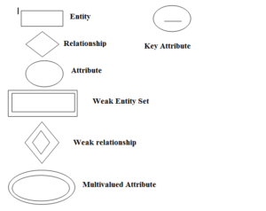
- Multi valued attribute: These attributes contain multiple values. T is represented by double oval.For Example ‘Phone Number’ of an entity “Student”
- Derived attribute: The attributes which are derived from other attributes & are not present in the database system are known to be called as Derived Attributes. For example The ‘Age’ of the entity ‘Student’ can be derived from the attribute “Date of Birth”. So age is the derived attribute. Derived attribute is represented by dotted oval.
ER Diagram Notations and Symbols
Different er diagram notations and symbols are shown in following figure
Relationships between entities
If there are more than one entity in a DBMS, then there is a high chance that all the entities are related to each other, through some kind of relationships.These relationships are represented using a Diamond Shaped Box and as usual, entities are represented using Rectangular Box. All the entities in a relationship are connected using a hard line. When two entities are connected to each other, then it is known as Binary Relationship and the number of instance of any entity which can be associated with any other relation is known as Cardinality of the Entity. Relationships are basically the association between the entities.There are basically 4 types of cardinality of a relationship:- ONE TO ONE
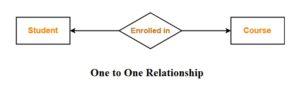
Example : One student can enroll in at-most one course or one course can be enrolled by at most one student.
- ONE TO MANY
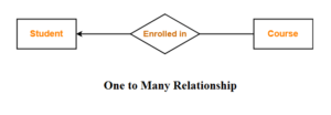
Example: One student can enroll in any number of course ( including zero) or one course can be enrolled by at most one student.
- MANY TO ONE
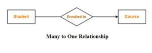
Example : One student can enrolled in at most one course or one course can be enrolled by any( zero or many) students.
- MANY TO MANY
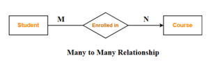
Example: One student can enroll in any number of course ( zero or many ) or one course can be enrolled by any( zero or many ) number of students.
ER Diagram Example with solution
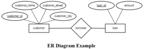
An ER diagram for Customer and Loan entity is as shown in following figure.
Relationship between customer and loan entity set is borrower. It means customer borrow the loan. Different attributes of customer and loan entity are also shown.
Customer_id is the key attribute of Customer entity similarly loan_id is the key attribute of loan entity.
ER Diagram Keys
In ER Modelling, Keys are used for indexing. Through keys, one can easily access any row without wasting much time and efficiency. It is very usable in the tables which millions of data or rows. Lets take an example of a table “EMPLOYEE” with the fields “EMP_ID, EMP_F_NAME, EMP_L_NAME, EMP_PHNO, EMP_EMAIL”. Basically there are 4 type of keys which plays the major role in ER Modelling, which are as follows:- Primary key: It is that column of a table which has all the unique values inside it. Through primary key, the data in the table will be identified uniquely.
- Composite key
Participation constraints in ER Diagram
There are two types of participation constraints and these are as followsTotal Participation
In total participation each entity is involved in the relationship. Total participation is represented by double lines in ER diagram. Total participation specifies that each entity in the entity set must compulsorily participate in at least one relationship instance the relationship set.
Total participation sometime also known as mandatory participants. Total Participation Example –In the following figure Double line between the entity set “Student” and relationship set “Enrolled in” signifies total participation.
Partial participation
In this types of participation not all entities are involved in the relationship. Partial participation is represented by single line. It specifies that each entity in the entity set may or may not participate in the relationship instance in that relationship set. That is why, it is sometime also known as optional participation
Partial Participation Example

Also Read : Blockchain’s Battle with Financial Inclusion — Part 1
