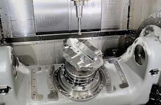
This article highlights the significance of custom milled turbine blades for cutting-edge performance. It uncovers how milling plays a critical role in the manufacturing of jet gas turbines.
Understanding Turbine Blade Design
The geometry of a turbine blade is a complex amalgamation of aerodynamic principles and material science. The blade is shaped such that it extracts maximum energy from fluid flow (air/hot gases). This curvature and twist of the blade is known as an airfoil, which is responsible for directing the fluid flow and extracting its energy.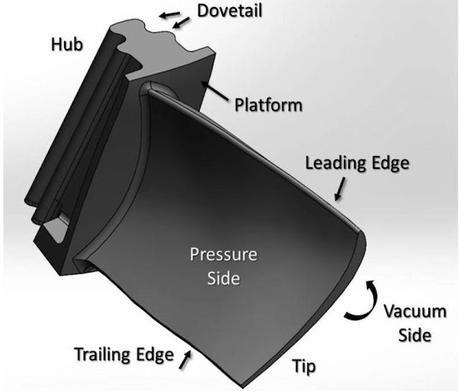 The lower part of the blade that connects to the hub is called the shank, which withstands all mechanical stresses and transmits rotational (power) to the hub, which then runs the engine compressor.
 The airfoil has two edges, leading and trailing edges. The leading edge is the front part of the airfoil that first contacts the fluid flow. It is designed for minimal drag and maximum fluid dynamics efficiency. The trailing edge is where the fluid exits the airfoil; it controls the wake and reduces turbulence.
The whole concept of energy extraction and blade design is based on the Euler equation (an extension of Newton’s second law). This equation relates the change in fluid momentum to the mechanical work done on or by the fluid.
Manufacturing Turbine Blades
Manufacturing of turbine blades involves precision engineering; the design has to be very precise with narrow tolerances. The process starts with preliminary design phases, where all design parameters are calculated, and a 3D model is constructed and analyzed. After that, the real manufacturing begins.Design phase (CAD and CFD models)
Initially, in the very early stages, we start with a simple 1D design that is on the turbine's middle area. This step doesn’t capture all flow details but gives a good starting point. Key parameters are set here based on each manufacturer's standards.The next step adds more detail by looking at changes along the blade’s length and radius. This 2D model helps us understand how work is distributed across the turbine. We calculate flow at different points, following the radial equilibrium equation.
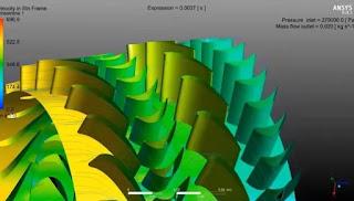
Then, a CAD model for the turbine blade is constructed and tested for mechanical and thermal stress. Next, CFD analysis is performed to check out how the design will behave in real scenarios.
Milling Techniques
After design, designers move to the manufacturing of blades. Earlier investment casting was used to make the blades and then machine them to get them to exact. However, now with the advent of 5-axis milling and adaptive milling, the raw alloy ingot can be directly milled and shaped into the blade with much better precision and accuracy.* 5-Axis CNC Milling
Traditional milling machines have three linear axes, (X, Y, and Z). With 5-axis milling, you get two additional rotational axes; that means the tool bit can work at any position and orientation to achieve the desired.
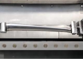
The process begins with a roughing face mill. In this step, the basic shape of the blade is cut from the material, removing a large amount of excess material. Next, the focus shifts to shaping the airfoil, particularly the pressure side. The 5-axis CNC bit precisely carves the curve surface of foil according to the feed dimensions. After roughing, the airfoil undergoes, semi-finishing where all the imperfections are removed. Slots are also created near the shank. The interface and shroud plane also undergo the finishing procedure one by one until the blade gets to its final form, where it looks like the 3D model you created earlier.
* Adaptive Milling
Adaptive Milling is another machining technique that has a role in turbine manufacturing. In this method, the machine adjusts the cutting process in real-time based on material variations and geometries.
Since turbine blades are made from advanced alloys which usually vary in hardness and texture. The adaptive milling CNC setup automatically adjusts the cutting speed and depth to accommodate these variations.
Similarly, the design of airfoil, especially has subtle curves and angular variations. Adaptive/programmed milling takes into these complex geometries and adjusts the tool’s speed, motion, and orientation accordingly.
Post Treatment
Machining operation mostly ends with CNC milling. Then, the blades are covered with a specialized coating for protection. For instance, they may be coated with thermal barrier coatings (TBC) or oxidation-resistant coatings for protection against heat and corrosion.The last step is quality control i.e. testing the final product. This is the most important step which ensures everything is according to the design specifications and meets the standards. Rigorous testing, which involves visual inspection, x-rays, and ultra-sonic tests, is done to approve the milled turbine blades for their assembly in the aircraft engine.
Why Custom Milled Turbine Blades
The final question is regarding the importance of custom-milled turbine blades. Why is the customization necessary?High Precision
Precision is the key in aerospace; a small deviation can potentially endanger the whole design and people’s lives. So, we need a unique milled blade that’s perfectly designed for specific engine models. The 5-axis milling technique helps us reach that level of customization and precision.Superior Material Usage
Turbine blades have to be made from nickel or titanium alloys. Normal milling methods may not be able to handle those. However, custom milling techniques are adept at handling these sophisticated materials. They make sure that the inherent properties of these alloys are fully utilized in the final blade.