What is an LED cube?
An LED cube is exactly what the name suggests: LEDs arranged in the form of a cube. Why is that good? Because you can run very nice 3D animations on it! It basically acts as a very low resolution 3D display. I suppose I could go on forever trying to explain what an amazing thing an LED cube is or how it’s a piece of electronic art, but it’s better if you just watch this video and see for yourself:
Are you amazed? Well, I certainly was when I had first discovered that LED cubes exist. They just looked so different from anything I had seen before. So… cool, so… futuristic… so… amazing! Naturally, I had decided that I just had to have one! But I did not know anything about them so I had gone through all the questions that somebody who does not know much about them would ask. In the following I’ll guide you through these questions (with answers, of course) and explain why if you want to have an LED cube, you have to build your own

Where can I get/buy one?
The short answer is: if you want a cube that is big enough to run really cool animations on it… you can’t really get or buy one. If you can be satisfied with a small cube (say 4x4x4 LEDs or 5x5x5 LEDs), you can search the Internet and you will find a few for sale. The prices will be up to around 100$. But if you are like me and you want one that is bigger and can display nicer 3D animations (say an 8x8x8 cube), then you will most likely not find any for sale or if you will, it will cost a small fortune. There are several reasons for this:
- Building an LED cube takes a lot of work. The few people and companies who do make them, will have to charge enough money for them to cover their costs (most of which will be in the work, although for bigger cubes the components can cost quite much too) and make a profit. That translates to the buyer paying a lot of money for the end product.
- Building an LED cube and running 3D animations on it takes a lot of technical knowledge, both in the hardware and software area. Not many people and companies have all this knowledge (compared to how many we are on the face of the planet) and even fewer will actually make them to sell them, because it’s a lot of work and few people will be willing to pay a high enough price for the cubes to be worth producing and selling.
- LED cubes are a relatively new thing. They have been around for only a few years, so maybe the big companies have not yet recognized the potential in their mass production (if there is any).
- LED cubes are quite fragile. Transporting them can be very problematic.
OK, so… if I can’t buy one…
How can I build my own?
Now this is certainly the million dollar question. Unfortunately the answer is very complex. But I can tell you from start that you will need to invest an immense amount of work and that you will need a huge amount of patience to get it all done. You will also need much time and one or two hundred dollars for components. Is this all worth it? Well… that’s for everybody to decide for themselves. I’d say yes. If you see the awesomeness in the LED cube and if you like building your own things anyway, if you are willing to spend hundreds of hours of work on it (I’m not kidding, it’s a big project) and if you can invest a little money too, then you can start dreaming about having your own LED cube. Make a hobby out of it and build it!
This article and the ones to follow are meant to make the job easier for you. I will try to synthesize all the information that is in my head about building an LED cube and serve it to you in a manner which will save you work, time and headaches, so that your cube will be completed faster and look better when it’s done. This is a project that requires more than basic electronics hardware knowledge and skills and also software development knowledge. If you’re a total beginner in any of these areas, then you’re in for a hell of a ride. But if you’re motivated enough, eventually you’ll pull through. With the software part you can cheat: I will make my code available for download so you can just use that for start and try to customize it later if you wish. So don’t let the fact that it’s hard to build an LED cube demotivate you. Good things usually take a lot of work, but in the end you will have something… magic!
So how does this thing work?
What we see as 3D animations running on the LED cubes are basically fast changing 3D patterns/shapes displayed with LEDs. What it all comes down to in the end is lighting the appropriate LEDs at the right time. It’s all about controlling the LEDs. For that you need a microcontroller, like an Arduino, for example. You can think of the microcontroller as the brain of the system. It’s basically a very small and very simple computer which runs the software that tells it which LEDs to light up when. It transmits some signals to a driver circuit which translates these signals into electric current passing through the appropriate LEDs. So, in other words the software decides which LEDs need to light up at a given moment of time, the microcontroller transmits transmits these decisions to the driver circuit in the form of signals and the driver circuit lights the LEDs up.
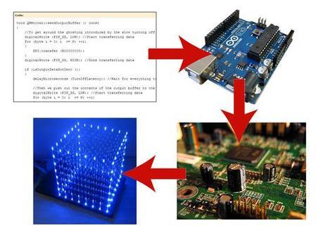
Once you get the hang of it, working with a microcontroller, programming it, is not that hard, especially if you have an Arduino, which takes the easiness one step further. They are also relatively low cost. There are many cheap microcontrollers and a typical Arduino costs around 30-40$. you can also buy Arduino clones, which are usually just as good as the original ones but twice as cheap. For example I use a Tosduino Mega 2560 with my LED cube.
How are the LEDs controlled exactly?
As stated before, running the 3D animations is all about being able to control the LEDs individually, lighting them up at the right times, in the right combinations. An LED has two legs: an anode (positive leg) and a cathode (negative leg). If the right amount of electrical current passes from one leg, through the LED, to the other leg, it lights up. So in order to be able to control each LED individually, you would need twice as many wires as LEDs (because they have two legs). But an 8x8x8 cube contains 512 LEDs, so that would mean running 1024 wires through the cube. That would certainly ruin the aspect of it and would also be next to impossible. And we did not see so many wires in the video. In fact we saw none. So how is it done?
The first trick is to use the legs of the LEDs to conduct electricity instead of wires. For example, if you solder the cathodes of all the LEDs which are above each other in the cube together (the cathode of the top LED to the cathode of the LED below it, that on’s cathode to the one which is one level lower and so on), then you only need to take a wire to the cathode of the lowest LED in the vertical column, the current will travel all the way up to the top LED through the cathode legs which are connected together. If the legs of the LEDs are not long enough to place the LEDs far enough from each other, you can use craft wire (beading wire) to fill the gaps, to take the current from one LED’s leg to the next LED’s leg. This is a strong metallic wire used by jewelry makers which has similar shine to the LED legs, so it will look nice. In most cases it is silver plated copper wire, which conducts electricity well, which makes it a good choice.
The second trick is to organize the LEDs into vertical columns and horizontal planes. All the columns will have the same polarity and all the planes will have the same polarity. For example we can form the vertical columns by soldering the cathodes together which are below each other and we can form the horizontal planes by soldering the anodes together which are next to each other. This way we will connect the anode planes to the positive voltage (+) and the cathodes to the ground (-) and the LEDs will light up. The images below show how to organize the LEDs into anode planes and cathode columns (the black columns are the cathodes connected together and the red planes are the anodes connected together).
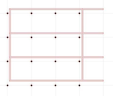
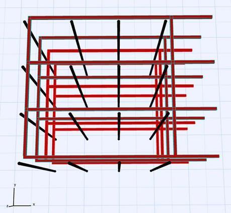
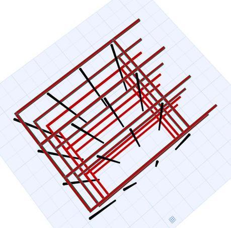
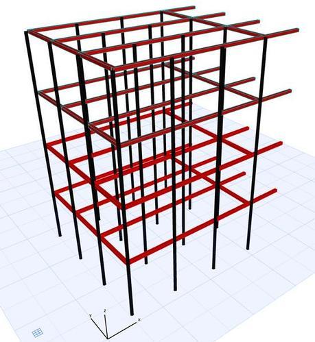
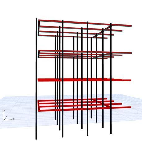
Note that the cathode columns and anode planes never touch. That would be a short circuit, not something that we want! Instead, at the intersections of columns with planes we have the LEDs, which will light up when the planes are connected to the positive voltage and the columns are connected to the ground.
OK, OK… but we don’t want all the LEDs to light up together. We want them to light up individually. No problem! If we want to light up for example the LED in the second plane and in the fifth column, we connect the second plane to the positive voltage and the fifth column to the ground and leave the rest unconnected (this will be the job of the driving circuit – to switch the planes and columns on and off). Similarly, if we want to light up the LED in the third layer and in the sixth column, we’ll connect the third layer to the positive voltage and the sixth column to the ground. Or if we want all the LEDs in the fourth layer to light up, we’ll connect the fourth layer to the positive voltage and all the columns to the ground. The LEDs which have their anodes connected to the positive voltage and their cathodes connected to ground will all light up. Easy enough. And we only need as many wires as columns and layers. In an 8x8x8 LED cube we will have 8×8=64 columns and 8 layers (horizontal planes). So we will only need 64 wires connecting the columns to the ground (which can easily be concealed in a box below the cube) and 8 wires to the horizontal planes. If we’ll use craft/beading wire for the planes (to conduct the electricity between the planes and the circuitry in the box below the cube), which has the same shiny appearance as the LED legs, they will go unnoticed.
Multiplexing
Let’s try to imagine how we could light up, using the method described above, two LEDs at the same time, one that is situated in the second layer and in the fifth column and one that is in the third layer and in the sixth column. We will need to connect the second and third layer to the positive voltage and the fifth and sixth column to the ground, leaving all other layers and columns unconnected. This will light up the two desired LEDs which are at the intersection of the connected layers and columns, but unfortunately it will also light up two more LEDs: the one from the second layer and and sixth column and the one from the third layer and fifth column. This is because these other two LEDs are also located at the intersection of the connected planes and columns. So using less wires than theoretically possible bites back and more LEDs light up than desired.
To get around this problem we will use something called multiplexing. A multiplexed LED cube is one in which only one layer is turned on at any given time. The layers are turned on one after the other (for example from bottom to top) so fast (each one is on for only a few milliseconds) that the human eye sees the cube as if all the layers were on. The technique relies on something called POV (Persistence of Vision). Fortunately for us, LED cube makers, when the human eye sees an image, that image persists on the retina for approximately 1/25 seconds (about 40 milliseconds). So if we turn on the LED cube’s layers one after the other fast enough, it will seem that all layers are on. This solves the previously described problem because if only one layer is on at a time then all we have to do is connect that single layer to the positive voltage and connect the appropriate columns to ground (the cathodes of the LEDs which need to be on in the currently lit layer). As we switch from one layer to the next one, we also change the grounded cathodes and this way we can achieve any pattern we want. Following our previous example, if we want the LED in the second layer and fifth column (2, 5) and the LED in the third layer and sixth column (3, 6) to appear as on, then we will ground the fifth cathode column when the second layer is on (connected to positive voltage) and we will ground the sixth cathode column when the third layer is on. The problem of the two other LEDs ((2, 6) and (3, 5)) lighting up is gone!
Another major advantage of multiplexing is that because at any given time only one layer is on, the maximum power consumption of the cube drops to as much as one layer can consume. So for an 8x8x8 LED cube, you’ll have to plan for a maximum current consumption equivalent to that of 64 LEDs instead o 512. This will allow the use of a power supply unit with much smaller rating (and price!) and generally less special, easier to acquire, cheaper components in the driving circuit.
You might wonder how we are going to switch the layers on and off fast enough. That’s a task for the microcontroller/Arduino. They are up for the job. An Arduino typically runs at 16 MHz (executes 16 million operations per second), so switching layers 25 times a second is really no problem. We will, however, want to switch layers even faster. 25 frames per second is just about the limit where the human eye starts to see flickering instead of LEDs being continuously on. But your brain might still be unconsciously suspicious even at faster rates. The faster we switch, the nicer and smoother the cube animations will look and even the brain will be convinced. I have found that keeping each layer on for one millisecond (1/1000 sec) leads to perfectly smooth shapes and animation. Even this is not a problem for he microcontroller/Arduino.
How many wires?
We have seen that, by organizing the LEDs into horizontal planes and vertical columns, we only need as many wires between the cube and the driving circuit as many layers and columns we have. So, for an 8x8x8 cube, we will need 8+64=72 wires between the LED cube and the driving circuit. We will also need just as many connections between the driving circuit and the microcontroller/Arduino if the driving circuit just “translates” signals of the controller to LED currents, the controller needs to be able to drive each column and layer independently. While having so many wires between the cube and the driving circuit is not a problem, having equally as many connections between the driving circuit and the microcontroller is impossible. Most microcontrollers (including the usual Arduinos) only have 10-20 pins that we can use to transmit signals to the driving circuit. Even the toughest, most badass Arduinos (like the Mega 2560) only have 54 available pins, which is still not enough…
Shift registers
Don’t worry, for every problem there is a solution. For this one in particular the solution is brought by shift registers (8-bit, serial-in, parallel-out shift registers, to be more specific). These shift registers are integrated circuits which can accept data in serial mode (data is fed to it on piece at a time, one piece after the other) and pass it on in parallel mode (all the data at once along several output pins). We will use them in our driver circuit to collect and store several signals from the Arduino and send them to the LED cube all at once. We will use 8-bit shift registers, which means that each of them will be able to store 8 signals received from the Arduino and send them to 8 LEDs of the cube, all at once. So, for 64 columns and 8 layers we will need 72/8=9 shift registers. The signals will be sent by the Arduino to the shift registers so fast (typically at 4 MHz, in other words at 1/4.000.000 sec) that even though it’s serial communication, from a human point of view it will appear to be instantaneous and all at once.
The communication between the Arduino and a shift register can be achieved with a minimum of 3 wires (3 pin connections). So that would suggest that for 9 shift registers we need 9*3=27 output pins from the Arduino. But things get even better! The shift registers can be chained together, meaning that you can send data from the Arduino to the first shift register in the chain and when the first shift register is filled up with 8 bits of data, it will shift out the data on its output pins right into the next shift register in the chain. When the second one gets full, it will shift out the data to he third one and so on. So, if we chain all the shift registers together, we will be able to control the whole cube with only 3 pins from the Arduino, regardless of how many LEDs there are in the cube, 512 or even more for bigger cubes. That’s just awesomeness in its purest form!
If you wish to understand in detail what shift registers are and how they work exactly, there is a most excellent video put together by Kevin Darrah which shows the workings in “slow motion”. The Arduino will do the same, only extremely fast. So watch this video, it’s well worth a few minutes of your time (thanks Kevin!):
Worrying about costs? Don’t! 8-bit serial-in, parallel-out shift registers are relatively cheap, you can buy them for a few bucks a piece, so i’t's not a problem that for the 8x8x8 cube we need 9 pieces.
What are we going to build exactly and how?
In the following articles I’m going to walk you through the steps of building an 8x8x8 single color LED cube. We will cover both the hardware and software side of the process, focusing on the hardest parts. The things that we will discuss are applicable to smaller cubes too (2<=N<=8, where N is the size of the cube) and, with a few exceptions, even to larger cubes (N>8).
Our cube will be driven by an Arduino and we will write the code that runs on it in the C++ language, uploading it onto the Arduino on a USB port, using the Arduino development software. I will provide the code that takes care of the multiplexing and an animation framework, which can be modified and extended arbitrarily.
The frame of our cube will be built using craft wire (beading wire). Although the frame will not be as straight and good looking as if we soldered the legs of the LEDs together directly, I prefer this method because it let you space the LED further apart. In an LED cube visibility into the depth of the cube is very important and the distance of the LEDs influences that very much. Unfortunately, using additional wire to build the frame does mean more work and somewhat higher costs.
We will build an LED cube in which the layers will be formed by the LED anodes and the columns will be formed by the LED cathodes. Usually people do it the other way around, but with our components this is the approach to take. We are going to use N+1 TPIC6B595 shift registers in our driving circuit to switch the N*N cathodes and the N anode layers after collecting several signals from the Arduino, and NDP6020P MOSFETS to switch the anode layers, allowing up to 20 mA of current per LED. The communication between the Arduino and the driving circuit will be achieved through SPI, using only 3 connection pins (MOSI, SCK and SS).
Some advice
- Use 3 mm LEDs in your cube. Unless you place the LEDs very far apart (which makes the building process harder and the storage of the cube more problematic), 5 mm LEDs will make the cube seem crowded.
- Use diffused LEDs instead of clear ones. Yes, clear LEDs look nicer when they are not on, but most of their light goes out through the top of the casing. This doesn’t only mean that the cube will not be as bright when viewed from the side (and an LED cube is almost always viewed from the side), but also that the LEDs in lower layers will whine through the ones above them, which will seem like the higher LEDs are lit when they actually are not. This is definitely not a desired effect!
- Place the 3 mm LEDs approximately 3 cm apart to obtain a cube with enough space in it to easily see the LEDs in the back too.
- Use some kind of helper jig (perhaps a piece of wood) to hold the LEDs in place while you solder them. You will also need small crocodile clips and/or some hair clips to keeps the LED legs and the craft wire together while being soldered.
- If your soldering skills are weak, spend some time learning how to solder well before starting the cube. It is very important to avoid cold joints in the LED cube. After putting the layers together, the LEDs in the middle will not be accessible, so if a joint breaks, it will be a huge problem. Good soldering avoids this. I recommend to apply some liquid flux onto the joints before soldering, and to always use solder which has flux inside its core. Here’s a useful video showing how to solder correctly:
- Don’t try to build a big (8x8x8) cube as your first attempt to build an LED cube. Start with a small one (a 4x4x4 for example). There are many things during the build process which you need to try on a test cube before going for the big one. No amount of theory can prepare you for all the difficulties encountered during the build process, you need to experiment and see for yourself. You need to start with a small cube, which will not turn out perfectly. Check out this video of my 4x4x4 test cube. You can see that it’s not perfect, but it turned out alright:
- Although standard LEDs are usually rated at 20 mA, design your cube for much less current. For super bright standard white and blue LEDs 1.5 – 2 mA is quite enough. For orange, red, green and yellow ones the same value (or a bit more) should be good, but you’ll need smaller resistors as these colors have smaller voltage drops. See this table for the voltage drop of standard LEDs by color. Running the LEDs at full brightness (20 mA) will be a bit bothering for the viewers’ eyes and it will produce the unwanted effect of lower LEDs shining through the ones above them. Lower LED currents will also mean a more power-efficient cube, which can be connected to a lower rated power supply unit.
- The most important things that you need to build an LED cube are patience and perseverance!
So stay tuned for the detailed articles about:
- how to build the cube
- how to put together the driving circuit
- how to write software for it


