PART 3 – Structural Efficiency & Structural Artists
3. STRUCTURAL EFFICIENCY
3.1. Definition and key developments
French states that ‘nearly always it is desirable to use as little materials as possible both for reasons of economy, which apply no less in nature than in human affairs, and also usually for functional reasons‘(1988: pp. 105). With two decades passed since this statement, one would certainly also add to the list, the benefits towards sustainability. Historically, it was prevalent for structures to function in compression with the use of mass materials such as stone, masonry and concrete. In Spain Catalan tiles were used to great effect, as one of the first major development towards light-weight structures. Catalan tiles are structurally effective by the manner in which the tiles overlap one another, thus acting as a shell and working as a whole, eliminating abrupt interfaces and potential weaknesses, a phenomenon found commonly in nature (French 1988, p.117). This material was used by Gaudi to great success, whereby he explored the implications of form on a structures ability to resist forces. With the advent of steel, a material which exhibits a great strength to weight ratio and impressive tensile strength characteristics, a new age in structural efficiency was born, allowing light-weight structures capable of spanning great distances. As the dead-load of a structure often accounts for a major aspect of the forces it must resist, lighter structures can provide clear advantages, often reducing both; the lateral thrusts; the vertical structure requirements and the size of footings. Garlock et al. (2009: pp.42) explains that enthusiasm for structural efficiency sprouted as ‘the spirit of rationality was popularised by Viollet-le-Duc giving it a theoretical justification. The innovation of the composite material; reinforced concrete was equally radical as that of steel, with steel and concrete in combination exhibiting greater capabilities then the materials are capable alone. Reinforced concrete with its ability to absorb tensile stresses due to the steel reinforcing and the plasticity that comes from concrete, allowed designer’s great new freedom in form.
Despite the many advantages for structural efficiency Remo Pedreschi highlights that from an engineer’s perspective, ‘we always find that the most magnificent forms are resistant to simple analysis, and we will have to do a quite a bit of simple analysis before we can achieve the most sensible and responsible way to calculate these structures’ (Anderson 2008: pp. 141). Dr. Werner Sobek, Engineer and Architect, states that “to design minimal weight structures, for engineers, is one of the most difficult things to do” (Woodruff 2008). The added complexity often associated both in designing, calculating and constructing the complex structurally efficient forms lends rectilinear forms to remain most prevalent, despite their inefficiencies. In nature an increase in complexity is a process of evolution, evolving from simple to more complex forms over time (Thompson 1917: pp.217) towards continual improvements. Despite the added complexity associated with curved forms in the built environment, as biologists refer in nature, ‘successful body designs and behaviours must be high in information content,’ (Benyus, 1996: p.274) a key to survival and suited directly to function and place. As mankind continue’s to press the earth’s limits, the importance to develop more structurally efficient forms and forms better suited to place and function, is critical as a matter of our survival. An emphasis on intelligence and quality rather than production is a characteristic of stable and mature systems in nature (Benyus, 1996: p.96) and needs to be the path we follow. Advancements in computer software will aid the designer and engineer in unravelling the complexity although the intuition of structures from the designer will remain paramount.
Structural efficiency is achieved by making the materials ‘work as hard as possible’ (Anderson 2008: pp. 141), within parameters of safety, achieved by ‘aligning the elements of a structure along lines of force’(Anderson 2008: pp. 74). Apart from achieving great economy and being environmentally sensible, Dieste appreciates that this pursuit is also conducive to producing beautiful forms.
Rowland Mainstone has developed three criteria he believes to be important in the development of new structural forms. These are as follows;
i. Intuitions of structural behaviour: a spatial awareness of stability and the geometry of structures, and a feel for the nature of the forces in a structure; a muscular, physical sense of structure.
ii. Intuitions of structural action: a more refined view of structural behaviour, the basis of the mathematical analysis of structure; the description of behaviour in the quantitative terms of forces and moments, stresses and strains
iii. Intuitions of structural adequacy: a quasi –empirical view of structures, based on experience and practise.
(Anderson, 2004: p.138)
The latter two are beyond the scope of this thesis, with intuitions of structural behaviour the primary focus for this work.
3.2. The influence of form
ARCHES
Materials commonly used in the past such as stone and masonry are poor in tension and therefore the arch which works in pure compression allowed these materials to span over spaces. The laws of physics permit that materials will seek equilibrium by finding their lowest point of resistance, and thus the arch due to the influence of gravity will create downward and lateral thrusts which need to be resisted for the arch to maintain its shape. If the lateral thrusts from the arch are not resisted, the funicular shape, which is the most efficient form for an arch will be lost and the form will act rather as a curved beam, taking on bending, which was absent in the funicular form (Torroja 1962: p.88) . A funicular curve is one which is exhibited by holding a chain at two ends. In the example of the chain the curve acts in tension. The arch is therefore this shape reversed curving towards the sky to act in compression. The catenary curve is most efficient funicular shape for an arch of equal thickness acting only under its dead weight (Torroja 1962: p.90) but as Torroja highlights heavier materials tend to demand higher curves as to reduce the magnitude of lateral thrusts which could become excessive (Torroja 1962: p.89). The lower the funicular profile of the curve, the higher the compressive forces and the greater the lateral thrusts. Traditionally lateral thrusts were absorbed by massive walls or buttresses or in the case of vaults which act like a series of arches, the vaults were often placed beside one another to counter one another’s thrusts. For Gaudi the addition of lateral supports was seen to be a structural flaw and he sought to discover an arch form which required no additional lateral support. His experimentations and use of graphic statics allowed him to align the thrusts with the supporting columns (Anderson 2004: p.71) and he was able to merge the columns seamlessly into the arch form developing what Descharnes et. al (1971: p.54) describe as an ‘oblique parabolic order’.
Anderson (p.140) highlights that for arches the greater part of the stresses are due to its own dead weight and therefore can benefit significantly from lighter materials. Lighter materials therefore allow lower funicular profiles with greater spans more feasible as the reduced lateral thrusts can be absorbed by steel ties acting in tension between the arch ends or through modest lateral supports. Whilst the case, like Gaudi, the structural artists that followed viewed these additional supports as a structural flaw and sought to overcome forces through form alone.
SHELL STRUCTURES
Like arches, the deadweight tends to produce the greatest stresses in shell structures, especially in roofing applications. Like arches a lighter profile therefore becomes beneficial to the structure as it must withstand less force and can therefore span greater distances. Garlock (2009) describes the remarkable phenomenon of shell structures, stating:
‘it may seem counterintuitive that thinner structures when properly formed can lead to surfaces with lower stresses, but this is a structural truth discovered in the late 1920s by Robert Maillart.’
Whilst the case, as the shell becomes lighter the risks of buckling will increase commensurately. The addition of bulk or the use of stiffening ribs can satisfy this problem although for structural artists both provide inadequate solutions. For structural artists the risks of buckling can be overcome through the use of form alone, namely through the use of double-curvature, which provides the form with the necessary rigidity. The stresses in shells tend to be significantly more complex than arches or vaults and with double-curvature this becomes increasingly apparent. In Candela and Dieste’s shells they sought optimum efficiency with the objective to create what Garlock et. al described as ‘a proper shell,’ whereby the shell functions according to the membrane theory. The membrane theory is where the forces (compression or tension) are carried in uniform throughout the thickness of the shell without any bending, made possible by the shells correct geometry (Garlock et. al, 2009: p.77). In an appropriately designed shell, the structure will work according to the membrane theory whereby an unevenly distributed load will be spread across the thin shell surface. The result is a form of great structural efficiency as large loads are resisted by a thin shell. Often with shell design the most problematic areas whereby tensile stresses will be greatest is where the shells connects its supports and it is common for additional reinforcing to be located at these articulations (Garlock et. al, 2009: p.123). Specific examples of shells will now be discussed in relation to the innovations of key structural artists.
3.3. Structural Artists – Gaudi, Torroja, Dieste and Candela – from straight-lines to curves
GENERAL INTRODUCTION
Structural artists are those who have dedicated their working lives towards the pursuit of structural perfection. It is common as Anderson (2004: p.94) highlights for a structural artist to concentrate on one specific material and extend the materials known capabilities. Whilst the methodology of structural artist’s such as Gaudi, Torroja, Dieste and Candela varied, what they all shared was an intimate understanding of the construction processes, a sound understanding of structural behaviour and an artistic discrimination, which allowed their structures to be elevated to works of art. A view shared by Torroja, Dieste and Candela and earlier touched on by Mainstone’s three aspects of structural innovation is the importance in which intuition plays on the development of structurally efficient forms. Dieste for example, was quite critical of the education of engineers, whereby he believed students were exposed to mathematical formulas and computer modelling but failed to gain a true understanding of structural principles. As Torroja states;
“Complex and abstruse mathematical calculations are not alone sufficient to lead to conception of a structure or to guide the hand in tracing its outline: intimate and intuitive comprehension of its working forms is also needed” (Torroja 1962: p.8).
Intuition, was particular emphasised by Candela whereby in his work he generally avoided complex calculations, favouring more simple formula supported by his sound understanding of the forces at work (Garlock et. Al 2009).
A remarkable aspect in the work of structural artists, apart from the beautiful and elegant forms created, is the economic credentials of their structures in comparison to the more conventional alternatives. The economy of these structures was achieved through the efficient use of materials, often the replication of forms and formwork and their constructability, often adopting forms generated from straight-line generators to create great complexity.
GAUDI
QUADRATIC RULED SURFACES
As earlier stated the use of ruled surfaces was a favourite practice of Gaudi. One of Gaudi’s best examples was the sinuous curved roof of the schoolhouse adjacent to Sagrada Familia as seen in Fig. 7. It is apparent that the structure had a great influence on Dieste as seen in figure.8. From the central beam of Gaudi’s roof outward the form was taken by Dieste for the walls in the Church of Christ the Workers, both adjusting the orientation of the line generators to create undulating parabolic curves. In both, the sinuous curves provide the forms with rigidity reducing bending by the deep profiles in the roof and providing lateral stiffness in Dieste’s walls. Ingeniously Dieste’s undulating wall follows as Ochsendorf highlights the ‘moment diagram for a pin-supported portal frame under its own weight and therefore provides for an efficient use of materials’ (Anderson, 2004: 98) as seen in Fig. 9. The undulations of walls to resist lateral thrusts were also used in Gaudi’s schoolhouse although his undulations remain vertical rather than tilting back and forth. The undulating walls cleverly align with the troughs and peaks of the roof structure to act as tympanum, which perhaps allow the forces to be spread more evenly across the roof surface rather than favouring the valleys.
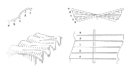
Fig.7 Gaudi’s schoolhouse adjacent to Sagrada Familia. Source: (Garlock et. Al 2009)
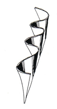
Fig.8 Dieste’s ruled surfaces wall – Source: (Anderson: 74)

Fig.9 Dieste’s Church of Christ the workers – Form follows the bending moments diagram. Source: (Anderson, 2004, p.98)
Gaudi also used ruled surfaces also for the generation of hyperbolic paraboloids which was to be another form highly influential to his predecessors.
TORROJA
The material which Torroja focused much of his efforts was reinforced concrete. A major development by Torroja according to Garlock et. Al (2009: p.45) was the realisation of the connection ‘between the stresses in a shell and the reinforcing that needed to be placed in it.’ Torroja was thus able to create smooth shells not visually expressive of the forces. The freedom to add reinforcing locally and directionally, as well as the freedom to shape reinforced concrete to the desired form to resist the subjecting forces was an aspect that made the material especially favourable for Torroja. As Torroja comments ‘unlike rolled steel, concrete is not available in definite shapes listed in a catalogue; its forms and dimensions must be designed’ (Torroja, 1962: p.58) providing a designer with great freedom. Reinforced concretes ability both in compression and tension, also makes it economical for members which must resist both as ‘the system needs to be designed to withstand what the material is weakest’ (Thompson, 1917: p.676). One of Torroja’s most notable designs the Madrid Hippodrome as seen in Fig.10 and Fig.11, which adopts the hyperbolic paraboloid, a form used by Gaudi and was later extensively used by Candella.
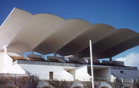
Fig.10 The Madrid Hippodrome. Source: (http://lastoria.forumfree.it/?t=32270001 20/8/2010)
HYPERBOLIC PARABOLOIDS
Hyperbolic Parabaloids or Hypars are generated by two paraboloids intersecting perpendicular at their centre, with their curves facing opposite directions as seen in Fig.11, creating an arch in one direction and a cable in the other. A major advantage of hyperbolic paraboloids is that the complex double curving form is constructed from straight-line generators, allowing great economy in construction, whereby conventional straight boards can be used for formwork. As Candela concluded “of all the shapes we can give to the shell, the easiest and most practical to build is the hyperbolic paraboloid” (Garlock et. Al, p. 138). Furthermore, the double curvature provides great depth in form allowing hypars to be resistant to bending. With the cable acting in tension and the arch acting in compression (Anderson, 2004: p. 42) the opposing phenomenon’s work effectively together to maintain a stable form, providing stiffness as the two attempt to flatten against the resistance of the other. In Torroja’s Madrid Hippodrome as seen in Fig. 10.
As seen in Fig.12 he takes full advantage of this phenomenon allowing the cable to cantilever over the grandstand acting as a beam as the force is channelled to the vaults, while the arch takes the load to the columns. The way by which Torroja balances the structure is quite ingenious with the roof form extending not quite as far in opposite direction but balanced through a tie, which connects to the weight of the betting hall arch stabilising one another while the arch of the stand acts as a flying buttress to balance the whole structure. If one considers the Hyperbolic Paraboloid in elevation one will also notice that the depth of the form is widest in the centre where the two paraboloids cross. This together with the upward curve makes the form ideal for cantilevering, as the wider centre which takes the force continuously narrows as it cantilevers outward in the same manner as the recurrence found in a tree, following the pattern of bending moments. Torroja further enhanced this phenomenon by reducing the section of the structure as it approaches its end where forces from dead-weight are lowest.

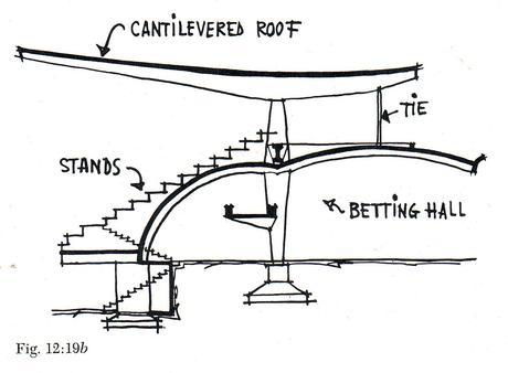
Fig.12 Section of the Madrid Hippodrome Grandstand. Source: (Torroja1962: p. 186)
Hypars were also widely used by Candela and was the chosen form for the Cosmic Rays Laboratory, which as a functional requirement demanded an extremely thin shell. The extreme thinness (5/8ths of an inch) of the shell significantly increased the risks of buckling. The hypars were therefore justified as the double-curvature would provide the necessary stiffness, achieved through form rather than mass. According to Garlock et. al in his quest to simplify calculations, Candella assumed the characteristics of a single curvature barrel shell, appreciating that the hypar would at minimum, act at least as equally well. Whilst Candella’s assumption was correct it should be noted that the forces in the two types of shells are distributed quite differently. As Faber highlights as seen in Fig.13 a barrel shell distributes the forces essentially in the same manner as a row of arches down its curve. A hyper on the other hand will distribute its forces in an oblique manner generally along the straight-line generators (p.91) and as force follow stiffness; the force is transmitted to the stiffer arches as explained in greater detail below.

Fig.13 Distribution of forces in the barrel vault compared to the hyperbolic paraboloid. Source: (Garlock et. al, 2009: p.91)
An article which was quite influential on Candella according to Garlock et al., written by K. W. Johansen ‘described how to analyse long cylindrical vaults, by treating them as beams with a circular cross-section (p. 65).’ If the same understanding is applied to the hyperbolic paraboloid, one can appreciate the advantages that come from the intersecting curves, which provides great stiffness allowing it to act similarly to a beam in both directions. As the greater depth of an ‘I’ beam provides it with greater resistance against bending, the same is true of the hyper and is why it is an effective form for cantilevers.
DIESTE
Born in Uraguay, Eladio Dieste focused on the development of the use of reinforced brick masonry, a material locally available and economical in its use. Whilst masonry bricks are traditionally brittle and poor in tension and bending, through the use of reinforcing and pre-stressing and thus imposing a state of compression working to the materials strength, Dieste was able to use brick in new forms and to span vast distances.
GAUSSIAN VAULTS
The Gaussian vault was developed from Dieste’s appreciation of how an arch is affected by bending. As Torroja (1962: p.167) states ‘bending stresses diminish and finally vanish in the proximity of articulations, yet increase in the intermediate zones.’ Aware of this phenomenon Dieste developed the Gaussian vault, relating the shells form precisely with the bending forces where the risks of buckling are highest. He achieved this form by increasing the depth of the section most at the spans centre through the use of double curvature and diminishing it to become flat as it approaches the articulations or wall. As Dieste states ‘it is to some exemplary individuals that we turn to renew our enthusiasm for inventions that are complex yet, once realized, possess a simplicity and seeming inevitability – for inventions that are not mere novelties’ (Anderson, 2004: p. 183), the Gaussian vault is certainly one of those ingenious discoveries. The Gaussian vault is made up of catenary curves working essentially as a ‘shallow barrel vault that acts entirely in compression’ (Anderson, 2004: p. 75) and thus does not require pre-stressing (Anderson, 2004: p. 144). What makes the vault unique is that the catenary curves are of varying rise, creating in cross-section an s-shaped band as seen in Fig.14. This s-shaped profile exhibits double curvature providing the necessary stiffness to resist buckling and thus allowing great spans with thin shells, his largest 180 feet (Anderson, 2004: p. 75). The form is highly practical both in its relation to the forces it must resist, but also, the repetitive use of the Gaussian form allowed the formwork to be re-used for the entire structure, making its construction economical. Furthermore, the highest catenary curve which rests above the lowest curve provides a welcome opening, allowing natural light to penetrate the interior. The form becoming flat at its junctions also makes the articulations between roof and wall simple. One aspect which no doubt would have displeased Dieste, was the need for steel ties to resist the lateral thrusts which as earlier highlighted can be large in long shallow vaults. As used in Gaudi’s schoolhouse undulating walls could provide a solution to resist the lateral thrusts although the complexity would increase significantly inevitably adding to the construction costs. The wall undulations could align with those of the roof to provide an elegant junction although special consideration would be required in regard to re-using the formwork. Dieste would have undoubtedly considered the many alternatives and whilst more elegant solutions are possible, the Gaussian vault was most successful for its economic credentials, being most widely used in factory applications. The tie is an economical solution although in the eyes of structural artists it is a flaw

Fig.14 The Gaussian Vault. Source: (Anderson, 2004: p. 74, 144)
CANDELLA
As a student Felix Candela was often disheartened by the mathematical complexity associated with the forms he so admired (p. 65). The greatest influence on his work, according to Garlock et. Al. (2009: p. 64) was Robert Maillart who ‘encouraged simplified calculations rather than rigorous analysis.’ This was to become the foundation for Candella’s work. Candella realised that to pursue his interest in form he would need to establish his own construction practice. Candela therefore developed his ideas and intuitive abilities through practice where his prodigious roofing around Mexico gave him some freedom for experimentation. Like Torroja, reinforced concrete was the predominant material used Candella.
UMBRELLA’S
Whilst taking inspiration from a sketch by Aimond, Candela was the first to construct the Umbrella form (Garlock et. Al. 2009: p.98). The umbrella is created by joining four straight-edged hypar surfaces as seen in Fig.15. As small hyperbolic paraboloids the stresses remain similar although the arrangement directs the forces into the groins and the cantilevering effect of the form creates tension at the outer edges as indicated by the arrows in Fig. These forces can be resisted through additional steel reinforcement or the use of small edge beams and Candela often thickened the valleys. (Garlock et. Al, 2009: p. 99).
Fig.15 Umbrella form. Stresses are greatest at vaults and can also be large at the distant corners. Source: (Garlock et. Al, 2009: p. 99)
As can be seen in Fig.16, the hypar quadrants, also referred to as tympans, are derived from straight-line generators. Through the repetition of the umbrella form over expansive spaces the re-use of formwork allowed great economies of scale and in Candela’s opinion ‘this form of roofing was cheaper than all others’ around half the cost of metal roofing at the time (Garlock et. Al. 2009: p. 99). It was common for Candella to tilt the umbrella forms as seen in Fig. 17 or use them in rows of varying size to allow the penetration of natural light. The rainwater was typically channelled down the valleys and into the columns which acted as downpipes. The highly efficient form was also used extensively by Candela for footings in the soft Mexican foundations (Garlock et. al., 2009: p. 68), spreading the load over a great area through a minimal use of materials.
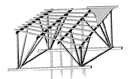
Fig.16 Construction of a tympan
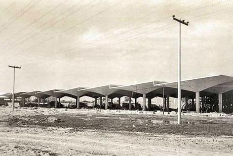
Fig. 17 Rio’s Warehouse, tilted to provide a roof with a sawtooth profile. Source: Garlock et. al, 2009: p. 99)
FOLDED HYPARS
Folded hypars are Candela’s adaptation of an Umbrella whereby in the words of Candella two tympans are joined “in such a way that one short edge of each hypar is horizontal to the opposite short edge of the vertical” (Garlock et. al, 2009: p. 122). The result is a form that shifts from a vertical orientation until it becomes horizontal as it cantilevers outward as seen in Fig.17. The twisting orientation alludes to an overall expansion of form creating a dramatic structure which appears to defy gravity, exaggerated from certain perspectives as seen in Fig.18. The folded hypar was not widely used by Candela in comparison to umbrellas, as the formwork and drainage is more difficult (Garlock et. al, 2009:p. 122), restricting its use predominantly for sculptural purposes or dramatic roof features as was used in La Candelaria subway station, Mexico. Despite horizontal planes being inefficient against bending, the momentary horizontality, seen in folded hypars, is made possible as the dead weight and therefore subjecting forces become reduced as the shell extends outwards. The horizontal orientation therefore carries only the forces from its own weight and benefits from the stiffness provided by the forms overall torsion. Horizontal only at the forms edge, it immediately begins to shift vertically in accordance with the increasing bending forces. As seen in Fig. 17, in elevation the folded hypar is in fact a direct representation of a bending moments diagram for a cantilevered beam, the forces by which the folded hypar assumes. The forces are directed to the valleys and the form becomes increasingly deep in section adopting the form of recurrence, efficiently shaping upward. As Garlock (2009: p. 123) states Candela ‘found that the stresses in the main body of the shell were negligible, and that the valley and the reinforcing steel at the support could be sized using the cantilever method.

Fig.17 Geometry of the Folded Hypar
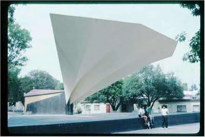
Fig.18 Folded Hypar – Santa Fe Bandshell. Source: (http://anengineersaspect.blogspot.com/2009/10/20-felix-candela-thin-shells-for.html, 4/8/2010)
HYPARS AND GROINED VAULTS
Los Manantiales Restaurant at Xochimilco is one of Candela’s most notable buildings and was the first groined vault attempted to intersect four hypars. In a groined vault, forces travel to the groins and are directed to the supports. Candella therefore thickened the groin sections and designed them to curve to provide continuity of the overall curved form.
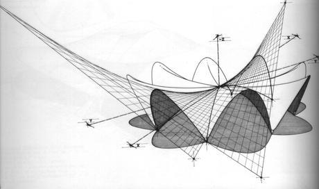
Fig. 19 Form of Los Manantiales Restaurant at Xochimilco. Source: (http://pc.blogspot.com/2006/11/restaurant-at-xochimilco-felix-candela.html, 22/09/2010)
3.4. The role of Computer-Aided Design and Computer-Aided Manufacturing
As French (1988: p.18) states ‘an engineer always has to balance manufacturing cost against performance, and so the components he designs have shapes which are easy to make, rather than the best for the task.’ This restriction toward complexity is foreign to nature, where form and performance is a matter of survival and where inefficiencies overcome by mass are understood to represent a false economy. As Benyus (1996: p. 254) suggests nature runs on information and mature systems favours quality rather than quantity. In our battle towards sustainability this shift towards more mature systems based on information and quality is paramount. In the building and design sector this is likely to be well bolstered by the advancements in Computer-aided design (CAD) and the development of Computer-aided Manufacturing (CAM). CAD software allows designers to realise increasingly complex forms and provides engineers with the tools to analyse them. To what would come as delight to Dieste, no longer do architects have the excuse to ignore the work of Gaudi or engineers being pre-supposed to posts and beams favoured due to the simple and reliable calculations. The age of computer-aided manufacture as Michael Stacey observed elevates the designer so they ‘no longer need to be remote from the manufacturing process; the 3-D model can become the building and all its component parts (Kaplinsky, 2006: p.67). CAM technology therefore lays an emphasis on design as the costs of manufacturing become reduced due to the removal of labour and the investment can shift to design, producing information rich, quality designs. Whilst an exciting prospect, CAM technology remains in its infant stages and as Kaplinsky (2006: p.68) highlights, at present, very few buildings are actually manufactured prior to even considering computer-aided manufacturing. In 1996 Benyus (p.116) described with enthusiasm the potential of 3D printers. Today, the clear advantage of this technology suggests that further advancements will be inevitable and the process will become possible on greater scales with the use of more robust materials. A great power of CAD software such as Microstations Generative components is its ability to use repetition and adaptable components which can rapidly speed the process of design and could allow components to be manufactured and later brought together to make the whole. What particularly excited Benyus (1996: p. 116) about CAM technology was the layering process of the manufacturing which could open endless possibilities in the use of composite materials as the technology continues to advance. With the design completed in its totality prior to its manufacturing there is also the potential of reducing wastage as the manufacturing can be better planned.
Despite the enormous possibilities presented by CAD advancements there remains some trepidation among the design and engineering community. As cautioned by Arup’s John Thornton ‘the danger is that computer power triumphs over design and takes away the need to simplify, rationalise and understand the material (Kaplinsky, 2006: p.68).’ Edward Segal also cautions, stating that ‘if used improperly, computers can lead designers to generate irrational forms that can be analysed and made to work but are not structurally efficient.’ Although Segal also accepts that ‘for rational designs, however, computers can serve a purpose’ (Garlock et. al, 2009: p.160). As with most technological advances the additional power provides a risk of being abused. The increasing ease of CAD technology makes the realisation of complex and seductive forms increasingly simple and there is a danger that this will over-ride the critical pursuit in which architecture is derived. Despite the potential benefits of digital technologies Dieste warns ‘the reader to exercise critical discrimination – between novelties and profound complex and responsible innovations’ (Anderson, 2004: p.17). The many advantages of CAD technology make its rise inevitable and when used appropriately could be an enormous boost in our battle towards sustainability. But as emphasised in the philosophy of biomimicry, technology must always be overlooked by a degree of wisdom.
3.5. The influence of Material innovations
As earlier highlighted a materials properties plays a critical influence on the structures potential forms and capabilities to resist certain forces. As Galileo had earlier hypothesised, and as summed up by Thompson; to overcome scales of magnitude ‘we either change the relative proportions, which will at length cause it to become clumbsy, monstorous and inefficient, or else we must find a new material, harder and stronger than was used before’ (Thompson, 1917: p.19). ‘Once reinforced concrete had been invented,’ as Torroja highlights, ‘it was possible to use its tensile resistance for much lighter structures’ (Torroja, 1969: p. 19) and therefore much greater spans were made possible. According to Mahmet Sarikaya ‘we are on the brink of a material revolution that will be on a par with the Iron Age and the Industrial Revolution,’ this age, as Sarikaya highlights will be one driven by biomimetics (Benyus, 1996: p.95). Tsui believes we are entering an ‘exciting and evolutionary point in our development of materials that approach the supreme efficiency of nature’s structures’ (Tsui,1999 :p.24). Material innovation is important not only to provide new possibilities in structural forms, but is also important in our quest to conserve resources, substitute non-renewable materials and provide building skins with an increased number of functions. In recent decades we have gone through what Benyus has labelled as the silicon age. Engineer and Architect Dr. Werner Sobek has explored the application of load bearing glues and states that his R129 prototype is the thinnest glass shell ever built. According to Sobek the shell thickness of ten millimetres with a span of eight and a half metres provides a relationship one tenth that of an eggshell. Sobek stipulates that the possibilities of such a shell could be spans as large as 20-25m. Despite this impressive feat as well as the many other material innovations, another idea being championed by Sobek is even more radical.
3.6 Alternative schools of thought to improve structural efficiency
The next step in structural efficiency according to Sobek is the idea of adaptive elements within a structure (Woodruff 2008). As ‘stresses follows stiffness’ (Anderson 2008: pp.223) the idea being championed by Sobek is for the a highly loaded member under the most stress to be artificially weakened, distributing the stresses more evenly to the neighbouring members. He suggests that if this is done in a clever way “you might save 50% of materials.” Essentially adaptive elements substitute material with very small amounts of energy to create subtle movements, which Chrisine Lemaitre says can “achieve a big change in the system.” In the quest for greater structural efficiency Sobek suggests architects and engineers should collaborate with aeronautical engineers who have focused their attention on this quest for many decades. Whilst adaptive elements suggest an exciting future for structural design, the complexity involved is likely to render it many decades from becoming feasible in a commercial sense. Much of Sobek’s work today as previously highlighted focuses on light-weight shell design using cutting edge materials.
Another exciting development in material innovation being explored by biomimetics such as Paul Calvert is the idea to learn from nature’s ability to self-assemble. As Benyus highlights;
‘whereas we spend a lot of energy building things from the top down-taking bulk materials and carving them into shape-nature does the opposite. It grows its materials from the ground up, not by building but by self-assembling.’ (Benyus, 1996: p. 104)
Whilst the idea of growing structure’s sounds like an idea of fiction, like 3D printers, the developments will begin at a small scale and one day it could be used to create much larger components or even buildings. The environmental benefits of such a breakthrough could be substantial. Structure’s that grow could expand forming to suite the forces in which they are subjected. Whilst distant propostions, the idea of learning from structural lessons from orchids could be applied to the built environment today.
